Light Refraction Index Determination: Difference between revisions
No edit summary |
|||
| Line 191: | Line 191: | ||
<biblist/> | <biblist/> | ||
[[Category:Light Microscopy]] [[Category:Schwarz,Hans-Jürgen]][[Category:Husen,Anika]] [[Category: | [[Category:Light Microscopy]] [[Category:Schwarz,Hans-Jürgen]][[Category:Husen,Anika]] [[Category:approved]] [[Category:R-MSteiger]] [[Category:R-CBlaeuer]] | ||
Revision as of 09:53, 20 November 2013
Authors: Hans-Jürgen Schwarz, Anika Husen
English version by Sandra Leithäuser
back to Polarized light microscopy
Abstract[edit]
Refraction of Light[edit]
The refraction of a crystal is determined by the properties of its lattice and can be estimated by using an immersion medium [Raith.etal:2009]Title: Leitfaden zur Dünnschliffmikroskopie
Author: Raith, Michael M.; Raase, Peter [1]. For this purpose, the crystal is embedded in a substance with a known refractive index. By means of different examination methods, it is possible to determine whether the crystal has a higher or lower refraction index than that of the immersion medium[2]. By comparison with several different known refractive indices, the estimation of the refractive index of the crystal can be effected. It should be noted, that birefringent crystals have different refractive indices at different orientations to the polarizers[3].
Becke-line test
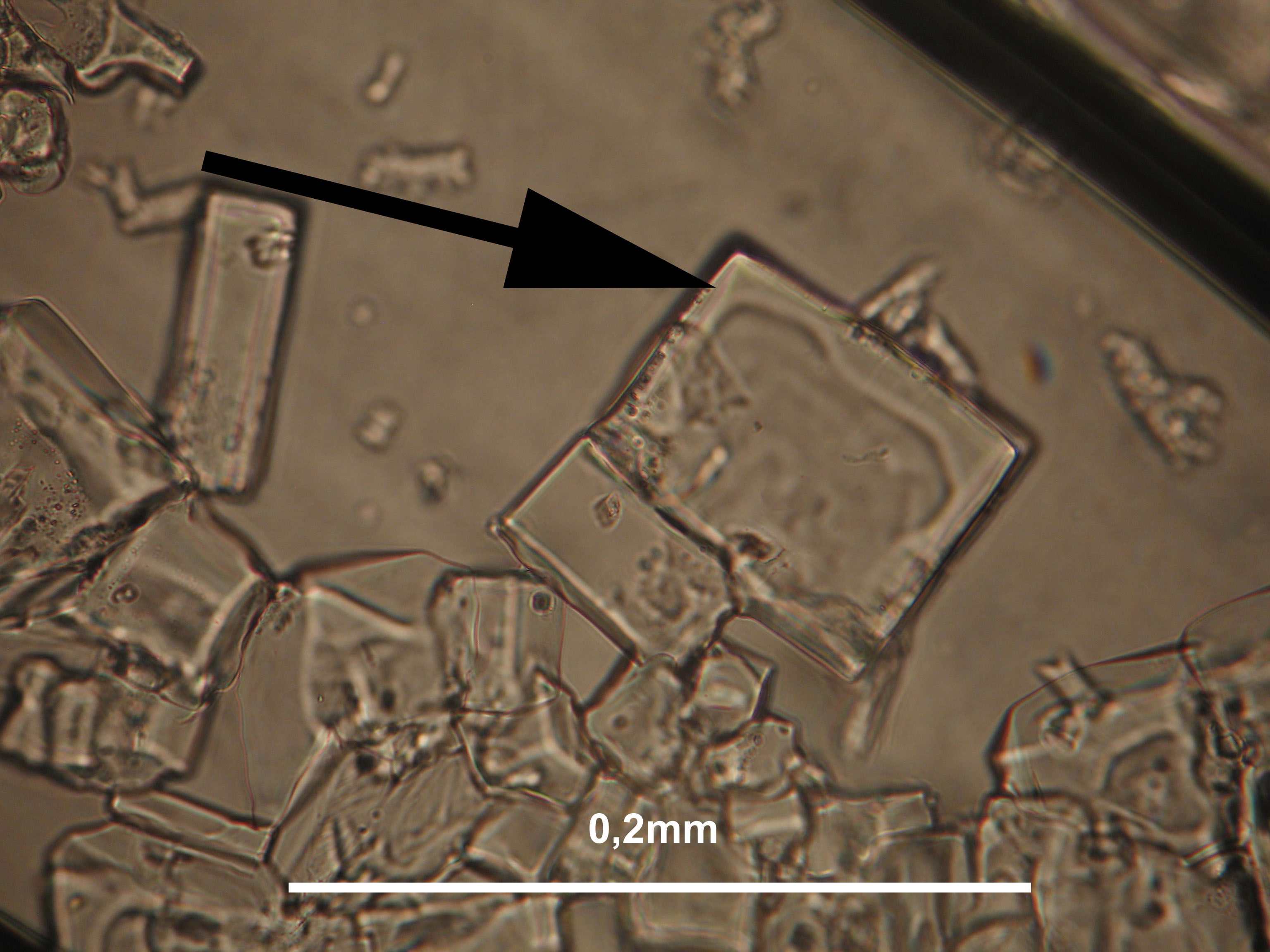
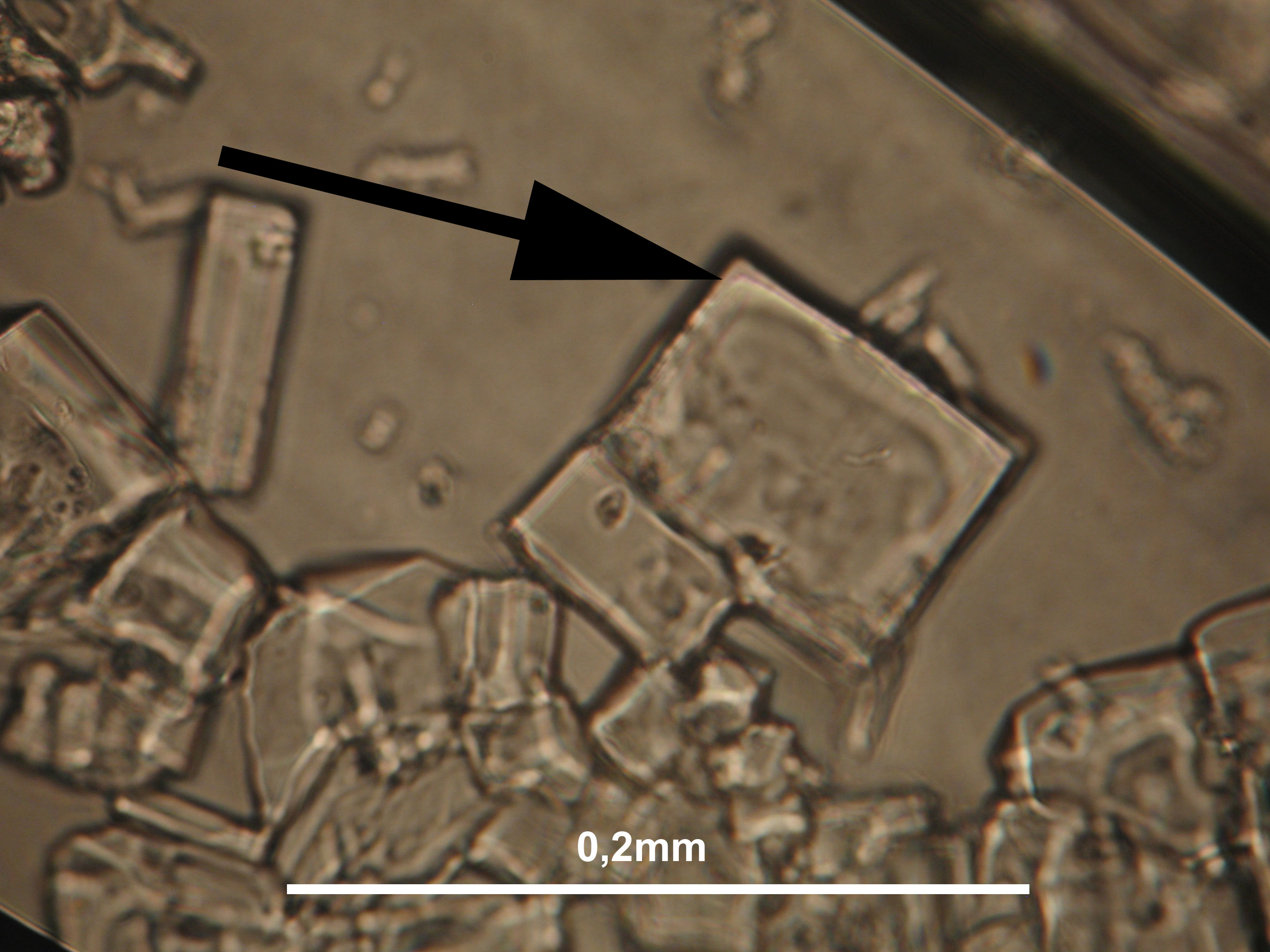
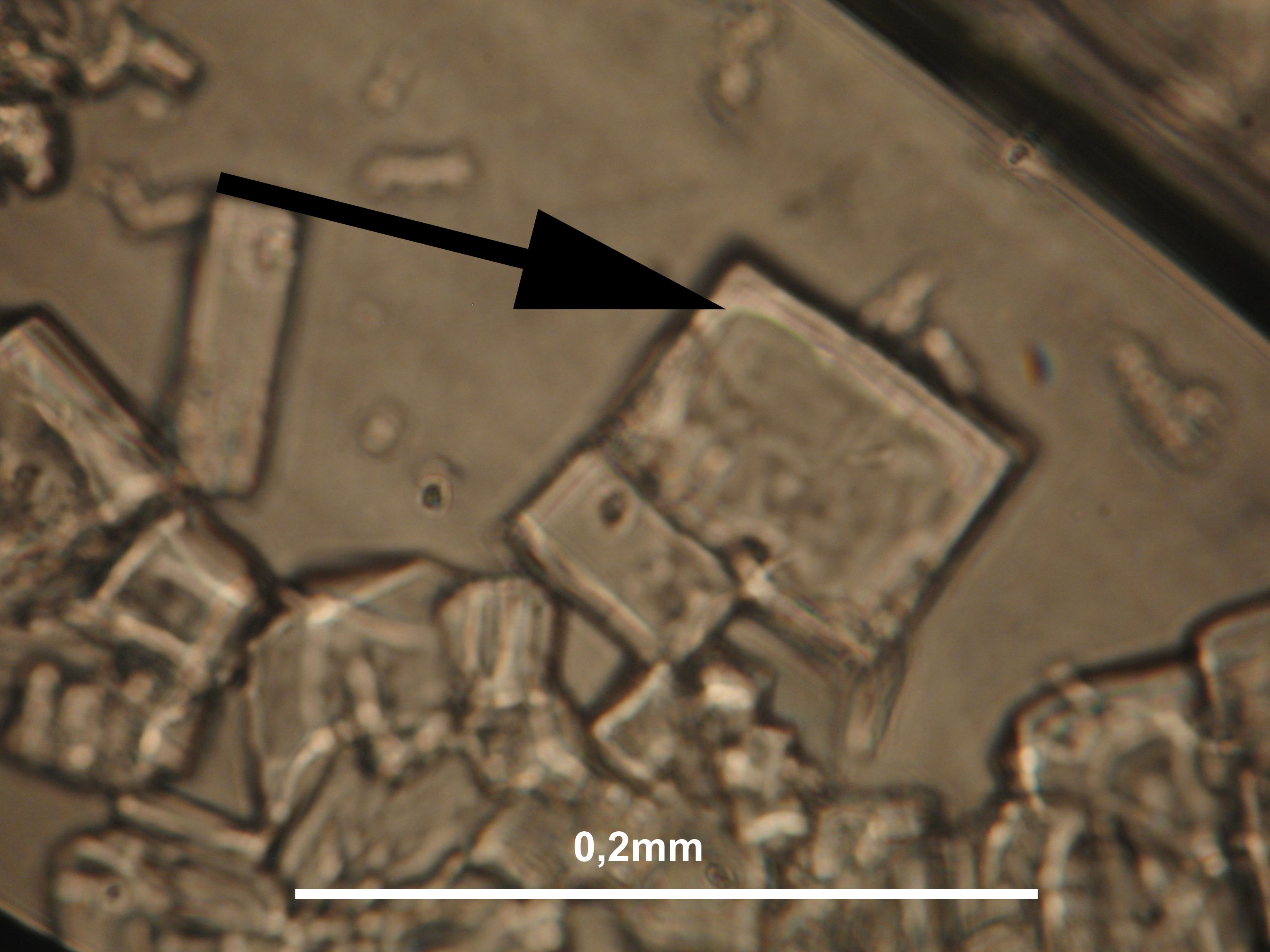
The Becke-line test is used to determine which of two materials has a greater light refraction. The Becke-line is a bright rim of light, visible along the mineral grain boundary when the grain mount is slightly out of focus. The Becke-line moves into the higher refractive material, when lifting the lens tube or lowering the specimen stage. If the refraction value of the two materials is the same, the Becke-line disappears as does the boundary between the grains. If the grain is colored but the immersion media not, only a colored cloud is seen. The less the two media differ, the weaker the Becke line.
The explanation for the appearance of the Becke-line is that the particle boundaries of crystals are rarely aligned parallel to the light ray. Because of the inclined boundary line, phenomena of refraction and reflection take place and the rays are focused so that the intensity of the light is increased along the boundaries.
Relief
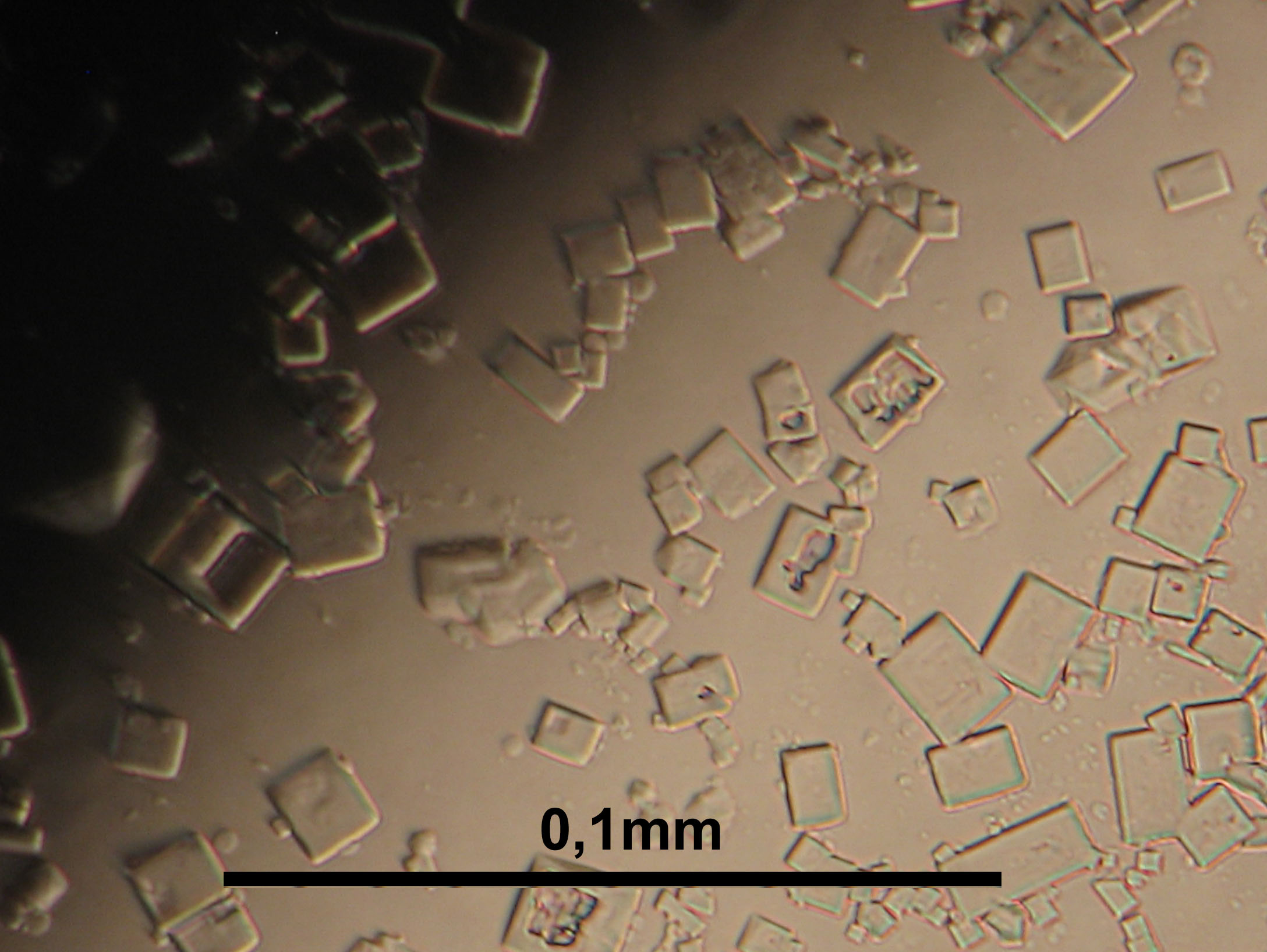
Due to the differing light refraction of a crystal and its immersion medium, an optical relief is produced, wherein the respectively higher refractive material always appears higher in relief. The higher the difference in refractive index, the more pronounced the relief will appear. The effect is caused by the reflection of light along the boundary plane[4].
Relief change
Birefringent crystals display two different refractive indices in every viewing direction. This can be ascertained by rotating the crystal on the stage of the polarization microscope to the oblique position. Because two different indices are always run through successively on rotating the crystal, the difference between the refractive index of the embedding medium and the crystal changes, causing a visible change in relief.
Summary of the most important points regarding the relief: 1. The development of the relief of a crystal characterizes the difference of the refractive indices, between immersion medium on the one hand and the index or indices of the crystal on the other. 2. A pronounced change in the relief of the crystal, while turning the rotation stage (in polarized light), characterizes a difference in the two refractive indices in a birefringent crystal (i.e.. birefringence).
Chagrin
The term chagrin (french for grained leather) relates to the appearance of the surface of a light refracting crystal. The higher the difference between the refractive index of a crystal and the immersion medium, the more pronounced the surface structure appears.
Schröder van der Kolk or oblique illumination method
The Schröder van der Kolk criterion is another method for the comparative refractive index determination of immersed particles. Contrary to the Becke-line test, which relies on a parallel and uninfluenced light conduction in the microscope's tube, the “Schroeder van der Kolk- shadow” is generated by manipulating the lighting. A partially attenuated lighting penetrates the particle at an oblique angle of incidence. This effect can be obtained by inserting an obstacle between objective and ocular. These manipulations cause the formation of a shadow, clearly visible on one side of the particle and always visible, if there is a difference between the refractive indices of the particle and the medium. Decisive is, that if the refractive indices of particle and medium differ, the shadow only appears on the side of either particle or medium.
The following rule applies: If the particle has a higher refractive index than the embedding medium, the shadow appears by the particle and on the side where the obstacle was introduced. The scientific explanation for this phenomenon (of partial shadow formation in cases of the explained manipulation of the lighting of the microscope) is based on the “rules of light refraction and total reflection”. [Nesse:1986]Title: Introduction to Optical Mineralogy
Author: Nesse, William D. If the particle has a lower refractive index than the embedding medium, the shadow appears by the particle at the opposite side to where the obstacle was introduced and in the media on the side where the obstacle was introduced.
Wave plate/ retarder[edit]
A positive determination of interference colors can be carried out by using a wave plate/ compensator. This device is made out of a material that has a specific birefringence. It can be added to the polarizer and analyzer, and fitted above the sample into the beam path. The wave plate is made in such a way, that, due to its birefringence, the interference colors can shift to exactly 550nm, i.e., the value of the deviation between magenta of the first and second order. This feature can be useful in determining the order of the interference color, because, by inserting the compensator, the interference color can be increased or lowered by one order, depending on the position of the crystal and wave plate to one another. Hereby the intensity of the color changes and both color orders can be matched by comparison. Moreover, the direction of the greater refractive index can also be determined with the wave plate. In doing so, the crystal is rotated to the bright position and the compensator is inserted (must be at 45° to the horizontal line). If the interference colors increase, the higher refractive direction of the crystal is parallel to the higher refractive direction of the compensator. If the interference colors decrease, the higher refractive direction of the crystal is situated by the lower refractive direction of the compensator. The directions of the higher and lower birefringence of the wave plate are usually drawn onto the compensator.
Immersion method[edit]
For the application of the immersion method, several different immersion media with a range of refractive indices must be available. In the analysis of salts, immersion media should meet the following basic requirements:
- For the salt analysis it is necessary to know and to guarantee the refractive index of a medium with an accuracy of 0.05.
- Only hygroscopic immersion media (like glycerine), or media mixtures with varying volatile components can be used, if their refractive index can be checked with a refractometer to obtain the required accuracy (see above).
- The immersion media should not dissolve the salt phases, or if they do, only very slightly. Therefore mo medium containing water can be used.
- The immersion media have to be transparent and non-toxic. They must not react with salts.
- Provided that solvents are used as immersion media, they must not be too volatile (the evaporation rate should be > 10, the vapor pressure < 100 hPa)
| Refractiv index nD at 20°C |
Immersion medium (volatile) | Immersion medium (not volatile) |
Comments |
| 1.32 | methanol | Source: Merck, Okt. 2000 Dissolves certain salts. | |
| 1.35 | acetone | Source: Merck, Oct. 2000 Too volatile for the use in microscopy. | |
| 1.36 | ethanol (absolute) | Source: Roth 1999; The index was measured with the refractometer. Dissolves some salts. | |
| 1.38 | propanol | Source: Roth, 1999; The index was measured with the refractometer. | |
| 1.388 | n-heptane | Source: Merck, Oct. 2000. | |
| 1.399 | n-butanol | Bezug: Roth, 1999; The index was measured with the refractometer. | |
| 1.41 | n-amyl alcohol | Source: Merck, Oct. 2000. | |
| 1.428 | petroleum | Pharmacy product, the index was measured with the refractometer. | |
| 1.446 | chloroform | Source: Merck, Oct. 2000. | |
| 1.45 | kerosene | Pharmacy product, the index was measured with the refractometer. | |
| 1.455 | glycerin | Source: Roth, 1999; The index was measured with the refractometer. Dissolves some salts. | |
| 1.46 | wallnut oil | Pharmacy product, the index was measured with the refractometer. | |
| 1.465 | caster oil | Pharmacy product,the index was measured with the refractometer. | |
| 1.47 | turpentine | Twice rectified, the index was measured with the refractometer. | |
| 1.474 | glycerin (anhydrous) | Bezug: Merck, Okt. 2000. | |
| 1.491 | toluene | Source: Merck, Okt. 2000. | |
| 1.505 | o-xylene | Source: Merck, Oct. 2000. | |
| 1.513 | iodoethane | - | Source: Merck, Oct. 2000 Too volatile for the use in microscopy. |
| 1.516-1.518 | - | standard Zeiss immersion oil | - |
| 1.53 | - | clove oil | Pharmacy product,the index was measured with the refractometer. |
| 1.55 | - | anise oil | Pharmacy product,the index was measured with the refractometer.
|
Weblinks[edit]
- ↑ http://www.dmg-home.de/pdf/Guide-print%20quality.pdf Michael M. Raith, Andreas Raase, Jürgen Rainhardt: Guide to Thin Section Microscopy
- ↑ http://www.mineralatlas.com/Optical%20crystallography/refractive%20index.htm
- ↑ http://www.olympusmicro.com/primer/lightandcolor/birefringence.html
- ↑ http://www.brocku.ca/earthsciences/people/gfinn/optical/222lect.htm
Literature[edit]
| [Mainusch:2001] | Mainusch, Nils (2001): Erstellung einer Materialsammlung zur qualitativen Bestimmung bauschädlicher Salze für Fachleute der Restaurierung, Diplomarbeit, HAWK Hochschule für angewandte Wissenschaft und Kunst Hildesheim/Holzminden/Göttingen, file:Diplomarbeit Nils Mainusch.pdf |   |
| [Nesse:1986] | Nesse, William D. (1986): Introduction to Optical Mineralogy, Oxford University Press |  |
| [Raith.etal:2009] | Raith, Michael M.; Raase, Peter (2009): Leitfaden zur Dünnschliffmikroskopie, online Publikation, Url |   |


