Birefringence: Difference between revisions
No edit summary |
|||
| Line 6: | Line 6: | ||
Birefringence or double refraction is a phenomenon in which a light ray decomposes into two rays, when it passes through the boundary surface of an optically anisotropic body. The two rays have a varying speed of light, depending on the direction of the wave propagation within the body. One of these rays is refracted normally (ordinary ray) and the other undergoes a change in direction (extraordinary ray). The [[retardation|path difference]] that arises between the two rays of different speeds, leads to interference colors. The majority of salts are anisotropic, i.e. a ray will expierience birefringence. Only materials with an interior structure that is attributed to the cubic crystal system are isotropic. | Birefringence or double refraction is a phenomenon in which a light ray decomposes into two rays, when it passes through the boundary surface of an optically anisotropic body. The two rays have a varying speed of light, depending on the direction of the wave propagation within the body. One of these rays is refracted normally (ordinary ray) and the other undergoes a change in direction (extraordinary ray). The [[retardation|path difference]] that arises between the two rays of different speeds, leads to interference colors. The majority of salts are anisotropic, i.e. a ray will expierience birefringence. Only materials with an interior structure that is attributed to the cubic crystal system are isotropic. | ||
<!-- | <!-- | ||
== Introduction == | == Introduction == | ||
--> | --> | ||
== Anisotropic bodies == | == Anisotropic bodies == | ||
Revision as of 14:55, 25 June 2012
Authors: Hans-Jürgen Schwarz, Anika Husen
back to Polarized light microscopy
Abstract[edit]
Birefringence or double refraction is a phenomenon in which a light ray decomposes into two rays, when it passes through the boundary surface of an optically anisotropic body. The two rays have a varying speed of light, depending on the direction of the wave propagation within the body. One of these rays is refracted normally (ordinary ray) and the other undergoes a change in direction (extraordinary ray). The path difference that arises between the two rays of different speeds, leads to interference colors. The majority of salts are anisotropic, i.e. a ray will expierience birefringence. Only materials with an interior structure that is attributed to the cubic crystal system are isotropic.
Anisotropic bodies[edit]
Salts can crystallize in different crystal systems depending on the arrangement of their ions in the crystal lattice. Specific crystal lattice structures will have different optical properties.
When light passes through the lattice of optically anisotropic materials, the light will be split into two shear waves with different speeds and thereby differing refractions. This phenomenon is called double refraction or birefringence (delta). This phenomenon was first observed for calcite crystals around the mid 17th century.
When light waves enter an anisotropic medium, not only birefringence, but also polarization takes place: both shear waves are altered in their vibration mode to such a degree that they are oriented perpendicularly to each other and vibrate only in one direction. They are now linearly polarized.
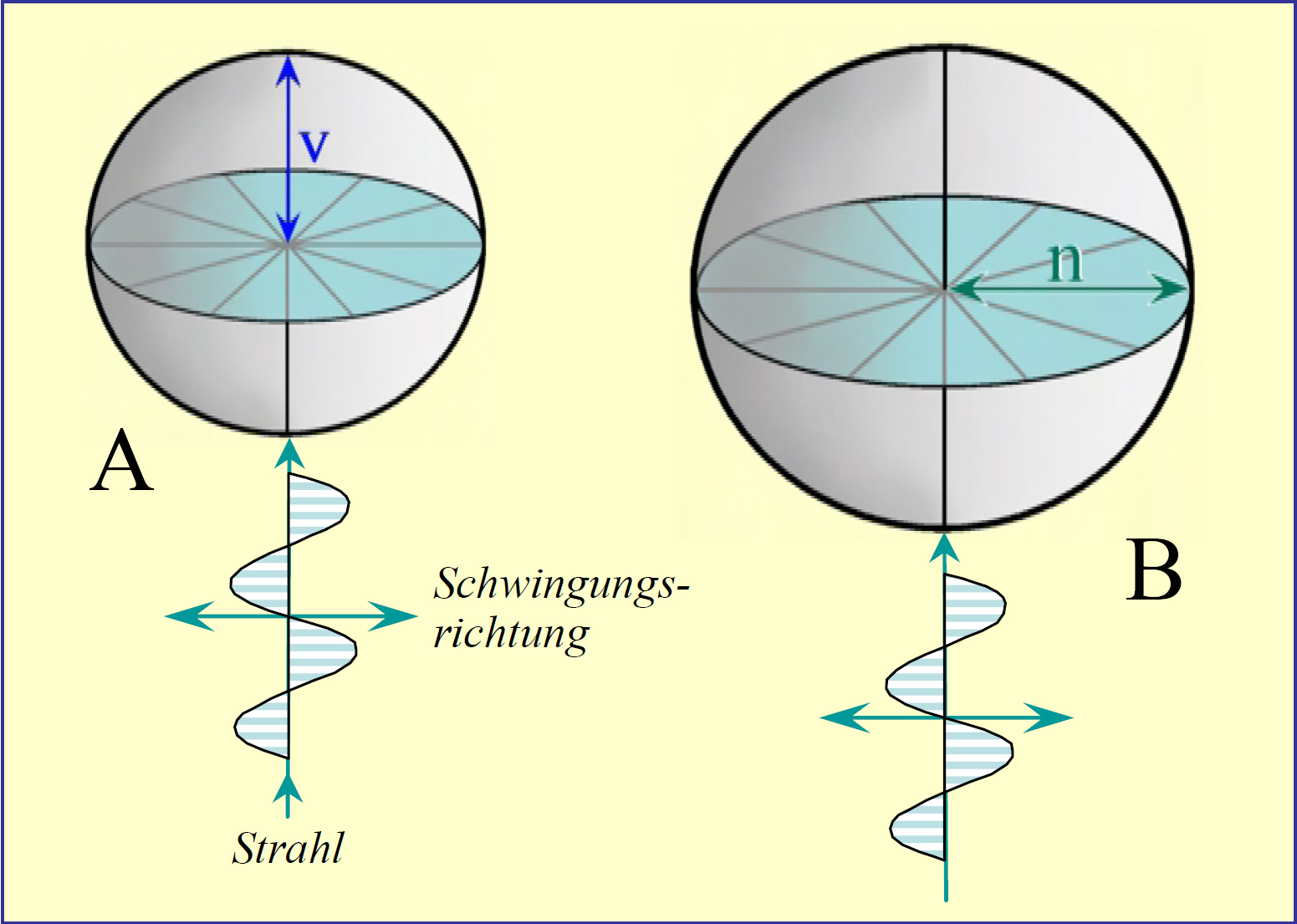
In an isotropic material the light waves will have the same velocity in all directions. Only materials crystallizing in the cubic system are isotropic. Imagining a model in which light radiates from the center of such a crystal in all directions, the shape of the light will be a sphere for the case of isotropic materials. This model is called indicatrix
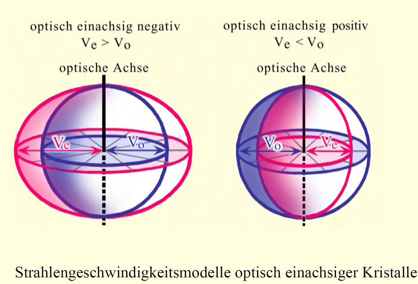
The indicatrix for hexagonal, trigonal and tetragonal crystal systems exhibits a biaxial ellipsoid of revolution. These minerals are described as optically uniaxial.
The indicatrix of rhombic, monoclinic and triclinic crystal systems is an ellipsoid with two optical axes, as the speed of light is different along the three axes. Minerals belonging to these systems are called biaxial.
Refractive Index- birefringence[edit]
The term optical density (absorbance) is used to describe the light velocity in a medium. Materials with a higher optical density have a lower speed of light. The value of the refraction/refractive index describes the ratio of the speed of light in a vacuum, to that in the examined body. The speed of light in the vacuum is fastest, so that all refractive indices of other materials are smaller than 1. The difference between the highest and lowest refractive index of a crystal is known as birefringence.
| Failed to parse (SVG (MathML can be enabled via browser plugin): Invalid response ("Math extension cannot connect to Restbase.") from server "https://wikimedia.org/api/rest_v1/":): {\displaystyle n_x = \frac{c_{Light}}{c_x}} |
| nx = Refraction of light, CLight = Speed of light in the vacuum, cx = Speed of light in the material X |

Author: Raith, Michael M.; Raase, Peter

Birefringence takes place on optically anisotropic (non- cubic) crystals, but it differs from the simple refraction of light. Refraction of light takes place at every boundary surface, between varying optically dense media, causing a deflection of the ray direction and the splitting into spectral colors. Birefringence is associated with a change in wavelength and the change of direction depending on it.
When birefringence takes place, the polarized light at the boundary surface of the crystal is split into two light paths. These undergo a change in polarization along the perpendicularly orientated transmission planes, forming the ordinary and extraordinary rays. The ordinary ray is refracted with the constant refractive index (no). The extraordinary ray has its polarization direction perpendicular to the ordinary ray and a refractive index (ne), that is dependent of its direction inside the crystal. The graphical representation of the different refractive indices into all spacial directions is the indicatrix.

Author: Raith, Michael M.; Raase, Peter

The refractive indices are shown as vectors taken from one point into all directions their length being proportional to their respective refractive index. When looking at optically uniaxial crystals, the indicatrix forms a spheroid with the optical axis as axis of the ellipsoid. The indicatrix of optically biaxial crystals forms a complicated double-shell model, and cubic systems produce a sphere.
Ordinary- extraordinary ray[edit]
Between the two rays that travel at different speeds, a path difference or retardation occurs. The path difference leads to a positive interference for the wave length, and the integer multiple of the wave lengths causes the retardation. Therefore the crystal appears in a specific color, described as the interference color.
Extinction[edit]
Depending on the orientation of the transmission plane of the crystal, it can be located in the dark (extinct) or in the bright position. The dark position re-appears four times at 90°, when rotating the crystal on the object table. In this position the transmission directions of the crystals are the same as the direction of the microscope polarizers. This results in the light not being re-polarized by the crystal, because light rays already vibrate inside a transmission plane, when they strike the crystal. Thus, the extraordinary ray is eliminated and the light meets the analyzer with simple polarization and perpendicular to its transmission plane. For this reason, the light, that has passed through the crystal this way, does not pass through the analyzer and does not contribute to the visible image. This phenomenon is called extinction.
When the crystal is orientated so that none of its transmission planes are parallel to the polarizer, birefringence or double refraction takes place. The elliptically polarized light that meets the analyzer is directed through the analyzer into a vibration plane making the crystal visible. The color of the crystal is the result of the retardation produced. The retardation is determined by the difference of the refractive indices in the direction of light transmission and therefore the value of birefringence. The intensity of the retardation is also affected by the thickness of the crystal, i.e., the distance the ray has to travel within the material.
The orientation of the dark position depends on the properties of the crystal lattice and it is therefore possible to draw conclusions about the crystal system. If, in the dark position, the crystal exhibits a parallel or perpendicular orientation towards the horizontal line, which is recognizable through the orientation of the cleavage planes or the habit, this is referred to as symmetrical or parallel extinction. If the orientation is in the dark position, but not parallel nor perpendicular to the horizontal line, the extinction behavior is called inclined extinction. Estimating the extinction angle can help to accurately identify a mineral.
Interference colors[edit]
In order to identify a phase, the examination of interference colors can be useful. These become visible under crossed polars and occur due to retardation, which is produced by birefringence. Depending on the magnitude of retardation, the crystal appears in a specific color in the dark field. The color appearance stands in relation to the wavelength, which undergoes a positive interference due to the retardation of the doubly refracted light. Hence, color and retardation are dependent on the refractive indices and on the thickness of the crystal. If the approximate thickness of the crystal is known, the refractive indices can be estimated by examining the interference colors. For this purpose, the bright position, i.e., the maximum birefringence is examined. The use of a color chart after Michel-Lévy [1] is recommended. It shows the correlation between interference colors with respect to the retardation or the refractive indices as a function of the thickness of the object.
Weblinks[edit]
Literature[edit]
| [Raith.etal:2012] | Raith, Michael M.; Raase, Peter; Reinhardt, Jürgen (2012): Guide to Thin Section Microscopy, Second Edition, online publication, Url, |  |